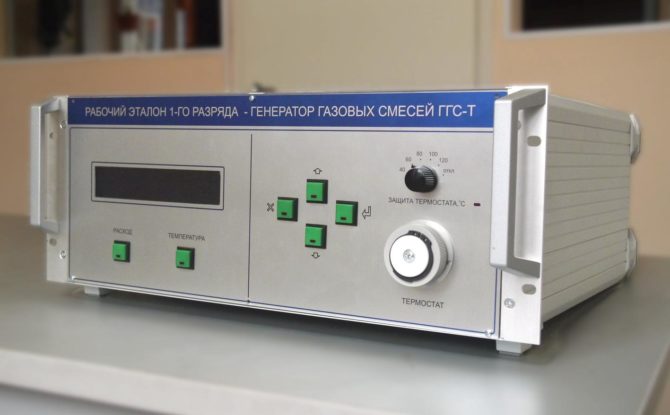
Gas Generators
- General Description
- Technical data
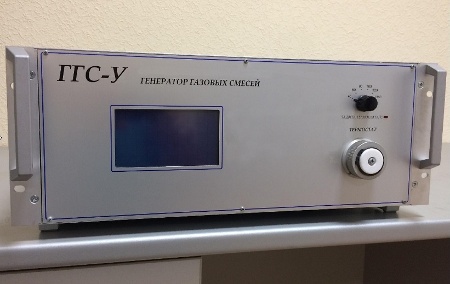
Mixed Gas Generators (generators of gas mixtures)
GGS are working measurement standards of the 1-st grade in accordance with the GOST 8.578-2008. Mixed Gas Generators are designed to determine unit of volume (mole) fraction and (or) mass concentration of analytes in binary gas mixtures. Generators of gas mixtures be used for the calibration and verification of gas analyzers, chromatographs, gas analysis systems, and gas analyzing transducers, as well as for scientific research.
Operating Principle
Generators are dynamic gas mixers. They provide preparation of binary gas mixtures in two ways:
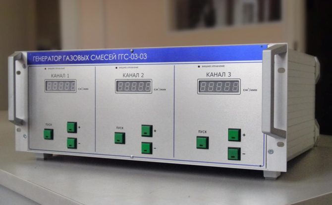
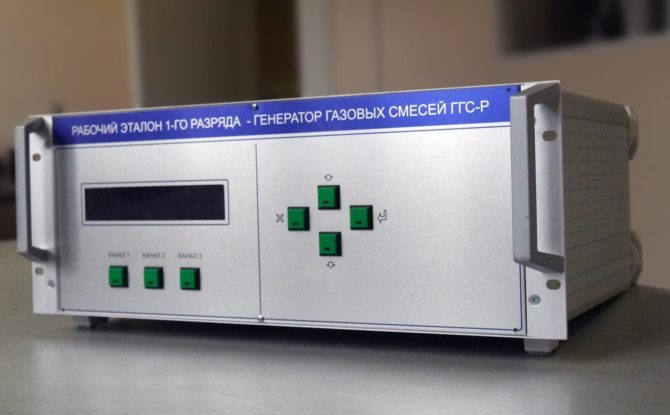
– by blending of pure gases or by diluting of intermediate gas mixtures (GGS-R, GGS-K, GGS-03-03). Regulation and measurement of flow rates of parent gas and diluent gas is carried out by means of thermal mass flow controllers;
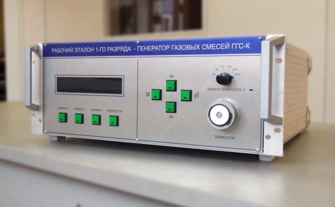
– by blending of gas streams, one of which (diluent) is regulated and measured by thermal mass flow controller, and the second (target gas) is defined by Permeation Tube (PM), located in a thermostat with controlled temperature (modifications GGS-T, GGS-K). PM is an ampoule with permeable wall, filled with a liquid or liquefied gas. At required temperature the substance diffuses through the walls of the ampoule in a flow of the diluent gas with constant rate, characterized by permeation rate of the tube.
Advantages
– High accuracy due to individual calibration of flow and temperature measuring channels.
– Individual configuration depending on customer requirements.
– Required values offlow rates inchannelsand values of volume(mole) fraction(or mass concentration) of components inthe prepared mixture are determinedby calculationin the manual mode(GGS-P, GGS-T, GGS-K, GGS-03-03), in autonomous mode using an internal controller(GGS-P, GGS-T, GGS-S) and in automatic mode usingan external control program(GGS-P, GGS-T, GGS-K, GGS-03-03).
– Microprocessor control of all the modes.
– Smooth setting of gas flow and temperature in thermostat (GGS-T, GGS-K).
– Additional independent protection of thermostat against overheating (GGS-T, GGS-K).
– Possibility of saving of few calibrations for various gases in the internal microcontroller (by request).
– Special software for Windows.
- GGS-R, GGS-K, GGS-03-03:
– Reactive gases (NO, NO2, NH3, Cl2, HCl, HF, F2 etc.);
– Sulfur-containing gases (CH3SH, С4H10S, C2H5SH, С3Н8S, CS2, COS, SO2, H2S etc.);
– С1 – С8 Hydrocarbons (CO, CO2, CH4, C2H2, C2H4, C2H6, C3H6, C3H8, C4H10, С6Н14, C5H12, C6H6, C7H8, C8H10 etc.);
– Halogen-containing gases (CHClF2, C2Br2F4, CHClF2, C2Br2F4, C2H2F4, C3F7H etc.);
– Inert and permanent gases (Xe, Ne, Kr,Ar, He, N2, O2, H2, etc.)
TECHNICAL CHARACTERISTICS
- GGS-T, GGS-K
Range of volume (mole) fraction of analytes, (GGS-R, GGS-K, GGS-03-03), 1.0·10-6 – 99 %*
Limits of permissible relative error of a setpoint value of vol. (mol.) fraction of analyte in a mixture at the generator output, (GGS-R, GGS-K, GGS-03-03) 2 – 5 %**
Playback Range of mass concentration of an analyte depending on a type
and permeation rate of a IM, (GGS-T, GGS-K) 0,00002 – 100 mg/m3
Limits of permissible relative error of generator working with PM,
(GGS-T, GGS-K) 3 – 7 %
Number of simultaneously used IM (GGS-T и GGS-K) from 1 to 6
Temperature setpoint range of thermostat, (GGS-T, GGS-K) from 30 to 120°С
Flow rate of a gas mixture at the outlet from 100 to 5000 sm3/min ***
Limits of permissible relative error of the volume flow rate ± (1.0-1.5) %
Power supply AC 220 V, 50 Hz
Dimensions, (LxWxH), mm, not more than:
For GGS-R, GGS-03-03 500ґ400ґ220 mm
For GGS-T and GGS-K 500ґ500ґ220 mm
Weight, , not more than: 15 kg
Average lifetime, not less than 8 years
Operating Conditions:
– Ambient temperature from 15 to 25 °С
– Relative humidity from 30 to 80 % at 25°С
– Amospheric pressure from 98.0 to 104.6 kPa
* – The upper limit of the playback range (99.0%) is valid only for the modifications GGS-R and GGS-K when calibration of generators was carried out on technically pure gases. Otherwise, the upper range limit of playback volume (mole) fraction will not exceed 10 %. The list of calibration gases is agreed with the manufacturer when ordering. The upper range of analyte volume (mole) fraction for GGS-03-03 is not more than 10%.
** – Limits of permissible relative error of volume (mole) fraction of analyte varies depending on the composition of the gas mixture, range and absolute error of analyte content measurement in a gas-diluent.
*** – Volume flow rate at the outlet, ranges of flow rate measurement and control may be changed depending on the technical requirements.

